Wake-up lamp – part I

Context

Our bodies have evolved to sleep during the night and wake-up as down starts to break. In the winter months, with sunrise happening later, most people will have to resort to alarm clocks ringing while it is still dark outside. This is a rough way to be awakened and can be depressing too. A wake-up lamp provides a more “natural” wake-up routine, simulating a sunrise by gradually increasing in brightness until full brightness, which coincides with the alarm time. This hack was inspired by a Philips product.

Hardware

Sonoff B1 smart LED light bulb

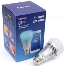
The wake-up light requires a dimmable light source; being able to control the color temperature is an added bonus, but not mandatory. For this project I’m using a smart LED bulb I had a few units lying around, the Sonoff B1 from Itead.

Replacing the B1 Firmware

To control the smart bulb from Home Assistant we’ll be flashing it with ESPHome. A couple notes: it is possible to integrate the LED bulb with Home Assistant keeping the original firmware unchanged; it is also possible to use Tasmota as the final firmware or as an intermediate in order to perform the first Over the Air (OTA) flashing, and then move to ESPHome. For this project I’ve decided to go straight to ESPHome and use it as the final firmware, same as other Sonoff devices I’ve modified earlier.

Flashing with ESPHome

The Sonoff B1 does not have header pins or thru vias to simplify the serial connection required for the first re-flashing; you’ll have to either solder pins for a temporary connection, or have a steady hand for holding a pin header bar against the pads for the duration of the upload. The schema for the serial connection is depicted below:

Wiring diagram for connecting a UART to the Sonoff B1 for replacing the stock firmware
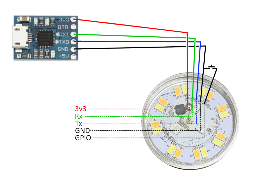
  • Note that the GPIO0 pin must be held to ground while booting in order to put the device in flash mode. It can be released after flashing is complete to allow a normal boot (and inspecting the logs)
  • While flashing the bulb must not be connected to mains power; it should be powered entirely by the 3v3 line from the UART adapter
  • Ensure that 3v3 power is used; feeding 5v to this device will damage it

More information about this procedure can be seen here: https://tasmota.github.io/docs/devices/Sonoff-B1/#serial-flashing

ESPHome Firmware

The following is a minimal ESPHome configuration for the Sonoff B1. For the full config used in this project refer to github here: https://github.com/heckler/esphome-device-configs/blob/master/wakeup_light_01r.yaml

esphome:
  name: wakeup_light_01r
  platform: ESP8266
  board: esp01_1m
  arduino_version: 2.4.2
wifi:
  networks:
    - ssid: !secret wifi_ssid_1
      password: !secret wifi_password_1
ota:
  safe_mode: True
  password: !secret ota_password
api:
logger:
  level: DEBUG
my9231:
  data_pin: GPIO12
  clock_pin: GPIO14
  num_channels: 6
  num_chips: 2
  bit_depth: 8
output:
  - platform: my9231
    id: output_blue
    channel: 0
  - platform: my9231
    id: output_red
    channel: 1
  - platform: my9231
    id: output_green
    channel: 2
  - platform: my9231
    id: output_warm_white
    channel: 4
  - platform: my9231
    id: output_cold_white
    channel: 5
light:
  - platform: rgbww
    name: wakeup_light_01r
    red: output_red
    green: output_green
    blue: output_blue
    cold_white: output_cold_white
    warm_white: output_warm_white
    cold_white_color_temperature: 6500 K
    warm_white_color_temperature: 2800 K

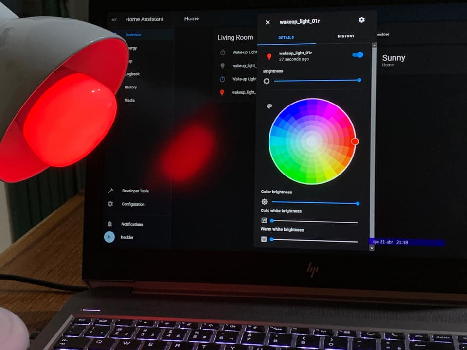
With the config above it is already possible to connect the device to Home Assistant and have full control of its different LEDs – the B1 have independent cool and warm white LEDs, as well as a set of low power RGB LEDs

Photo showing the B1 lamp glowing dark red, with a notebook screen on the background showing RGB light settings in the Home Assistant interface

The next post(s) will deal with the automation scripts in Home Assistant to create the desired sunrise simulation tied to a specific alarm time.

New irrigation pump for the balcony

Almost three years ago I’ve added an automatic irrigation system to take care of the potted plants in my balcony. Apart from having to replace the drippers due to UV damage earlier this year, everything is fine with this system.

But, it is always possible to improve on things. The little aquarium pump I installed in 2018 is ok, but not stellar; because it does not really manage to pressurize the water like, water does not so much “sprout” out of the drippers as it just, well, drips. With the current setup I water the plants for 1 minute every evening, and that is enough, but due to the low pressure, the water is discharged immediately under each dripper, which for a larger pot might not be ideal.

To try and solve this I’ve recently added a new, more powerful submersible 12v pump, and this post follow my first tests to try to measure it. On the advertisement it is said to be capable of moving one thousand liters of water per hour, which is quite impressive.

Water pump image with specifications printed underneath it

Results of some initial testing:

Currently installed pump45 liters per hour
New pump, with existing, narrow feed line72 liters per hour
New pump, with wide feed line (uninpeeded)452 liters per hour

My current setup is an irrigation kit with a very narrow water line, it’s internal diameter is just 4mm. This is not too relevant with the old pump, which has an outlet with only 5.8mm internal diameter; but the newer pump has an outlet with 10mm diameter, so the tiny hose becomes a choke point, as can be seen above.

The first result shows the flow rate of the original tiny pump, attached to the 4mm water line; not great, but has been keeping the plants alive for over two years now. The intermediate result, 72 liters per hour, is what we get with the new pump, coupled with the mini 4mm water line; an improvement, but clearly not ideal. Finally, if I attach the pump to a properly-sized hose, I was able to get 452 liters per hour flow. Does not match the advertised 1000 l/h, but perhaps this is due to the fact that in the test setup there was about a 50cm difference in height between the pump and the vessel for collecting the water.

Next steps: find a larger hose for replacing the water line in the system.

Smart Freezer – Part II

Collecting some data

In part I the temperature probe was configured to collect time-series data for the internal freezer temperature. The initial goal was to troubleshoot an elusive problem, and alert in case of over-temperature.

Here are some things which were learnt after the first 48h of data have been collected.

Normal operating ranges

The normal range of internal temperatures is colder than I intuitively expected. Of-course I knew that it had to be several degrees below zero degrees Celsius, but if I had to guess I’d say -5 to -10 would ok. Turns out that’s too hot for a freezer, it likes to stay below -15C (5F), with anywhere from -18C down to -25C being normal temperatures for my specific unit.

In the image below one can see the results of playing with different temperature setpoints in the front panel (markers 1, 2 and 3), as well as the quick temperature rise provoked by opening the door for a few instants (markers 4 and 5).

Also visible is the effect of the duty-cycle of the compressor, which stays on for a while (temperature drops) and then turns off for a while (temperature starts to rise). This is normal of models which don’t have an inverter compressor (one which can vary it’s speed to suit the instantaneous demands). On non-inverter models the temperature control mechanism on the unit (often just a simple thermostat) controls the amount of “cooling power” by changing the ration of the on cycle compared to the off cycle.

The head pump in action

A refrigerator is a form of heat pump: since it is not possible to create cold out of the blue (like you can with heat), the mechanism work by moving heat from the inside of the freezer into the environment outside. I had installed two sensors in this experiment, one inside the freezer, and the other outside, just above its metal body. Looking at the image below it is really easy to see the heat pump mechanism in action:

  • Every time the compressor turns on, the internal temperature starts to go down
  • Immediately, the external temperature starts to climb up
  • Once the compressor is turned off, the cycle reverts itself
  • Notice the range difference: for an excursion of approx 2C in internal temperature, the external temperature varies by just about 0.7C
    • This is easily explained by a combination of the much bigger volume outside, as well as the poor isolation of the room the freezer is in against its adjacent rooms

Duty-cycle in detail

The saw-tooth-like chats above show the effect of the on-and-off working cycle of the compressor. Zooming-in a bit it is possible to measure the time in each phase, as seen below:

Nenhuma descrição de foto disponível.

The image above shows in detail one particular moment. Changing the settings between “min” and “max”, the “ON” part of the cycle (compressor working, temperature going down) varied from anywhere between 20min to 50min (depends on how high the temperature was to begin with, how full/empty the freezer is, and if there are warm foodstuffs that still need to be frozen)

What did not vary perceptively though is the duration of the “OFF” phase: it was always around 21 minutes. This seems to suggest that this particular model (under normal circumstances) always shuts its compressor down for 21min, varying how long it keeps it ON in order to meet the demands of the moment.

Smart Freezer – Part I

The back story

The vertical freezer in our home has stopped working twice in the last six months (I’ll detail the probable cause in a separate post later). In both instances this was discovered before a catastrophic taw happened, but the safety margin was razor thin, and in any case, I decided to start watching it closely to troubleshoot and eventually call for repairs if needed. What I decided to do is to start monitoring its internal temperature (and eventually adding an alarm if it raised too much)

Smart temperature monitor

Since I run Home Assistant in the house, a natural fit is to use an ESP8266 board running an ESPHome-based firmware for data capture, and leave most of the smarts to Home Assistant. In the end I’ve decided to put together a device with the following basic features:

  1. Based on the NodeMCU development board (that’s my go-to ESP8266 dev board)
  2. With two Dallas temperature sensors (DS18B20), one for internal temperature, the other for room temperature (because why not?)
  3. With a piezo-electric buzzer, to sound an audible alarm in the device itself if needed, no external connection required
  4. With a status LED, for basic health info (in the initial version, using the on-board LED on the NodeMCU board)

First-versions need to demonstrate that the concept works, not necessarily be pretty or robust. This one is no exception: a breadboard-based mess of wires, glue and tape, but it works:

Image shows a breadboard with electronic components sitting atop a vertical freezer. From the breadboard a wire descends into the freezer itself.
First version of the temperature monitor
Close-up view of the breadboard, showing the NodeMCU board, some discrete components and the wire connections.
Close-up of the breadboard

In the close-up above it is possible to see that the NodeMCU variant used is the “V3” or “LoLin”, which occupies the whole width of the breadboard, hence the few jumper wires are connected from below the board, and not at its sides. The Vcc, Signal and GND connections for the two temperature probes are soldered to a 90-degree header pin and further held in place with hot glue. And finally, the buzzer itself is driven by a BC-547 NPN transistor so as to not overload the ESP GPIO, and has a flyback diode (1N4001) in parallel for protecting against induced voltage.

ESPHome firmware

The current version of the firmware is available on github here. It is fairly self-explanatory, the most important bits are below, with comments:

# Configure the Dallas DS18B20 temperature sensor platform on pin D7, GPIO13:
dallas:
  - pin: D7

# configure the two temperature sensors, with an alarm for the internal one:
# note: the addresses are device-specific, you need to query your own temperature
# probes to figure out their addresses and update your code accordingly
sensor:
  # inside temperature (sensor E - 0x28FFE382B11603B1)
  - platform: dallas
    id: freezer_internal_temperature
    address: 0xB10316B182E3FF28
    name: "Freezer Internal Temperature"
    on_value_range:
      - above: -10.0
        then:
          - script.execute: sound_alarm
  # outside (room) temperature (sensor C - 0x28FF1C8CB11605B0)
  - platform: dallas
    id: freezer_external_temperature
    address: 0xB00516B18C1CFF28
    name: "Freezer External Temperature"

  # NOTE: the sound_alarm action uses RTTTL to play a tune in the buzzer.
  # see the github link above for the details of how this is implemented

First results

Once connected to Home Assistant, instantly the current temperature is visible:

Home-assistant sensor info display reading "Freezer Internal Temperature -18.8 °C"

And with the sensor returning new samples every 60 seconds, HA starts logging the time-series data for you:

Home assistant sensor details with time-series chart

"17:46 Freezer Internal Temperature Freezer Internal Temperature 2 minutes ago -18.0"

Coming up next

Insights into the operation of the freezer and some cool notification automations in Home Assistant; also, a hypothesis on why the freezer stopped working twice in the last six months.